|
L10. 1. FSM adaptation. External interrupts (INT) [P10] FSM design programming in C. Detecting events (signal edges) using external interrupts. |
[3/12] |
3.5. FSM implementation in C language
3.5.1. Specifications
3.5.1.1. FSM concept adaptation to µC.
How to generate a CLK-like synchronisation signal when executing software? How to synchronise operations like state transitions in a FSM each time an active CLK edge is detected as it was done in Chapter 2? We will answer these important questions using an external CLK signal or overflow flags from embedded peripheral such TMR0 or TMR2 to generate interrupts to the main program. Therefore, we will solve two main ideas:
- Adapting a FSM in software, as a way to implement the same applications proposed in Chapte 2.
- Detecting signal transitions or events such rising or falling edges by means of interrupts to the main program.
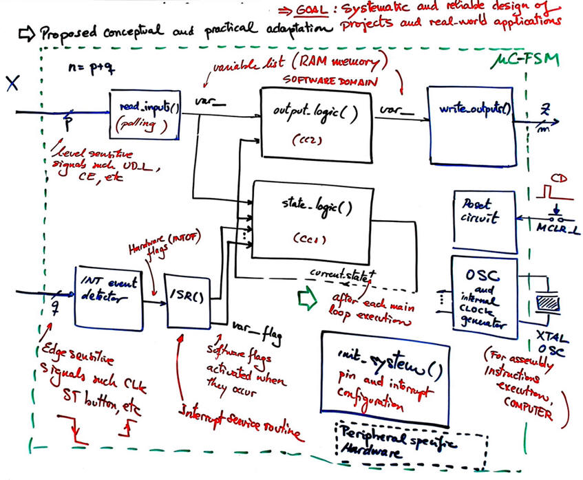
Such events will trigger hardware flags (INT0IF, INT1IF or INT2IF) that will the used in the interrupt service routine ISR() f to set our software flags (var_flag) that will run the state diagram.
In addition to external pins, many other peripheral subsystems (timers, A/D, USART, analogue comparators, etc.) will be able to trigger interrupt events.
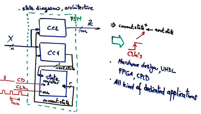
Fig. 1 shows Chapter 2 FSM architecture as it was studied and applied in many applications to solve sequential systems.
 |
| Fig 1. FSM architecture. |
Now, we propose to adapt the same architecture to software environment as shown in Fig. 2.
 |
| Fig 1. FSM adaptation rec: interrupts will allow detection of events (signal edges) and will make it possible to run state diagrams systematically programmed in C, as we did in Chapter 2. |
Current state as RAM memory variable.
3.5.1.2. CLK interface using interrupts
How to detect signal edges.
3.5.2. Planning
3.5.2.1. Hardware-software diagram
3.5.2.2. Interrupts: interrupt service routine ISR(). External event detection (CLK and push-button interface)
The key concept of external interrupt (INT) to the main program. Pay attention to the idea of external interrupt to detect a signal edge at the input pins and how they are handled by the μC in hardware (INT0IF, INT0IE, GIE) and once acknowledged at the ISR() software (Var_CLK_flag). The concept of the interrupt vector to execute the ISR() special function. The concepts of nested interrupts, stack memory and stack overflow.
Enabling and disabling interrupts in init_system().
3.5.2.3. output_logic() and write_outputs().
3.5.2.4. state_logic() and read_imputs()
3.5.3. Development & testing
References:
- Carmely, T., Using finite state machines to design software, EDN, March 30, 2009
- Bergfeld, D., Software design of state machines , Embedded.com, April 16, 2019
Exercise: Detect the duration of an active-low push-buttons PB_L click using two interrupt flags. How to configure int_system(), what is the software flowchart for ISR()? What kind of processing the FSM can do?
|
|
Questionnaire on P5- P6 - P7 -P8 (30 min.)


