|
|
Bachelor's Degree in Telecommunications Systems and in Network Engineering |
|
P12: Peripheral TMR0. Adapting dedicated processors |
| Resources in lectures and labs: | L12.1, Lab11, L12.2, L12.3 | Project | objectives |
|
|
Highlighted project: 4-bit serial transmitter with TMR0 (design phase #3)
or TMR2 (design phase #4)
1. Specifications
This is Serial_transmitter design phase#3: enhance Serial_transmitter_LCD replacing the external baud generator by an internal timer peripheral such TMR0.
-
Let us generate the baud rate timing using interrupts from internal timer peripheral TMR0.
-
Modify the hardware and delete the external CLK input.
-
Program the application configuring the TMR0 to generate the same var_CLK_flag variable.
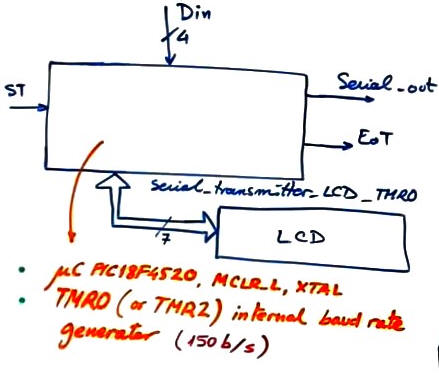 |
Fig. 1. Project s_trans_LCD_TMR symbol (entity name is shortened for not reaching Windows naming length limit). |
Timing diagram representing bit duration Tbit and the idea of starting to send data immediately after having detected the start transmission (ST) rising edge.
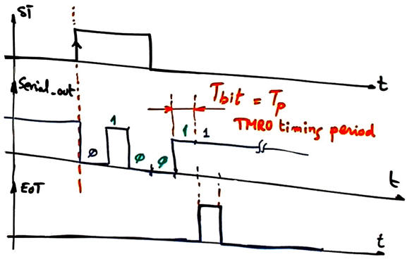 |
Fig. 2. Waveforms. |
Other design tutorials and assignments.
2. Planning
A) Hardware
The circuit is represented in Fig. 3. It is the same as in P11 without the external CLK oscillator for generating the bit rate.
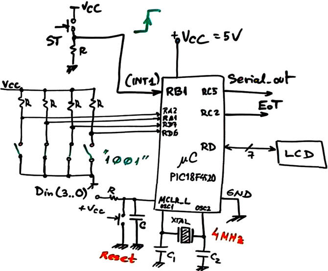 |
Fig. 3. Hardware circuit. |
Let us study the hardware of the TMR0 peripheral interpreting the datasheet diagram and configuration registers.
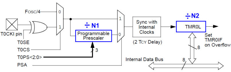 |
Fig. 3. TMR0 hardware in 8-bit mode from the PIC18F4520 datasheet. Study the TMR0 registers and configuration bits. |
B) Software
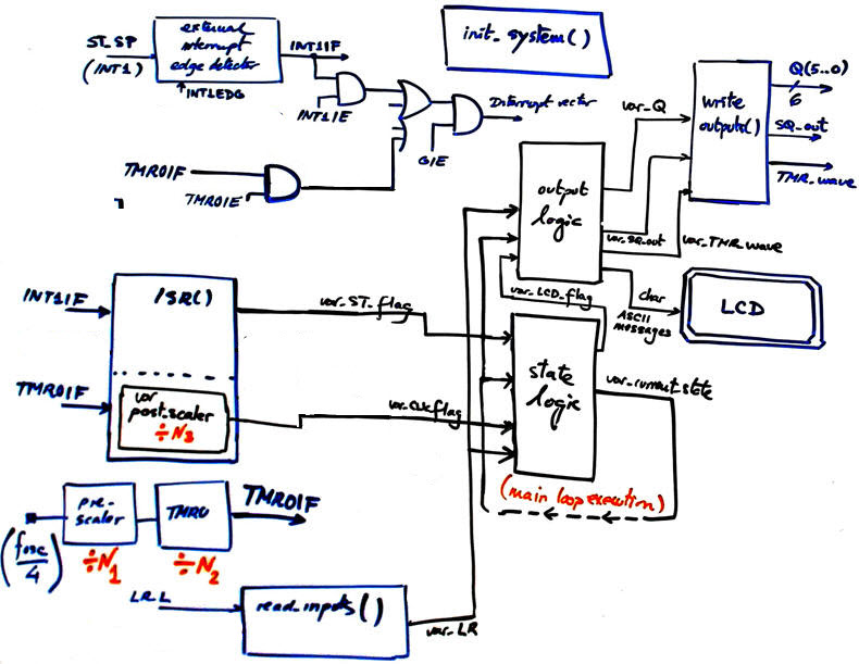
We intent to generate var_CLK_flag using internal TMR0. Therefore, the project has the same conception and only minor changes are necessary. When ST interrupt is detected, TMR0 will be switched on, configured and set as the bit time Tb source for transmitting bits. In the last state END_message TMR0 will be switch off.
|
Fig. 5. Software-hardware diagram when using TMR0. |
Design step #1. One idea is to use TMR0 in 8-bit mode. Infer N1, N2 and N3 values required in this application for generating a timing period Tp = 6.66666667 ms equivalent to 150 b/s, or the nearest value.
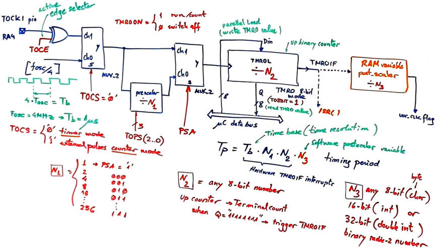 |
Fig. 6. TMR0 in 8-bit mode for generating a timing period of TP = 6.666 ms. |
The list of RAM variables required are shown in Fig. 7.
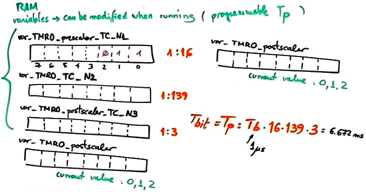 |
Fig. 6. RAM variables. Selected values allows generating 149.88 Hz (0.08% error). |
Design step #2. Is it possible to obtain more timing precision?. An alternative idea is to use the TMR0 in 16-bit mode, thus for timing 6.666 ms is not necessary to use neither the prescaler or the software postscaler, resulting in a simpler configuration because we can program var_TMR0_TC_N2 = 6666 obtaining even more precision.
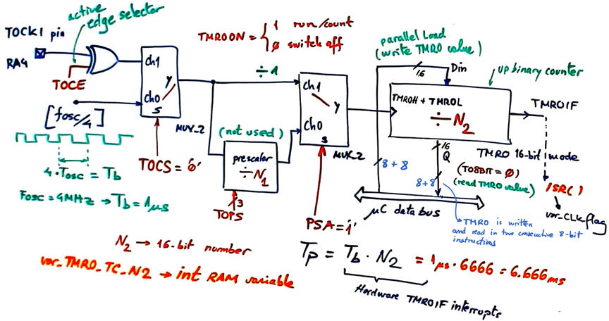 |
Fig. 7. TMR0 in 16-bit mode for generating a timing period of TPP = 6.666 ms. In this case, the bit rate is 150.015 b/s, (error 0.01%). However, instruction execution time imposes a time overhead that do not allow to reach such precision. TMR2 generates higher time precision due to an improved circuit with hardware parallel load. |
This is how the state diagram in modified for configuring and driving the TMR0. When timing period TP = 6.666 ms is reached, var_CLK_flag is set. The main idea now is to configure and start TMR0 when the ST edge is detected at the ISR() function., thus start bit will be send immediately after the ST active edge. Start_bit state will remain until the TP is elapsed.
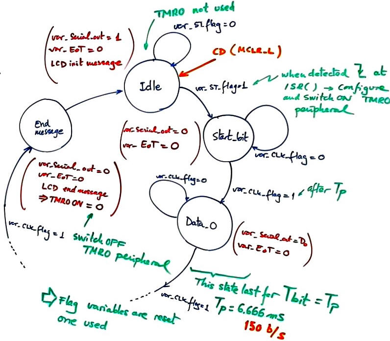 |
Fig. 8. State diagram modifications. |
We will draw only the function sections where the TMR0 parameters are set.
 |
Fig. 8. ISR() function flowchart. |
Project location:
C:\CSD\P12\s_trans_LCD_TMR0\(files)
3. Development and 4. Testing
A) Developing hardware
Project is renamed to shorten the folder path names and location.
This is the s_trans_LCD_TMR0.pdsprj circuit captured in Proteus.
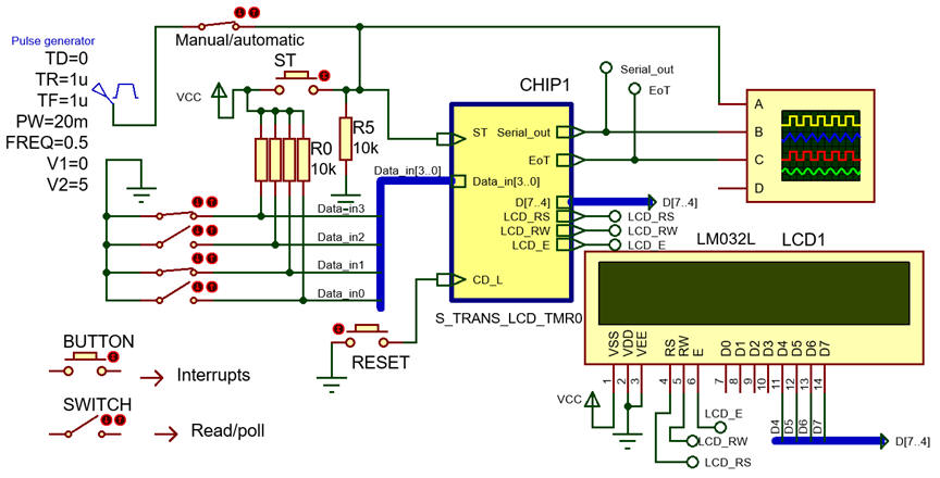 |
Fig. 10. Captured circuit. |
B) Developing software
This is the s_trans_LCD_TMR0.c source code. Remember to unzip LCD libraries in the project folder, two header files and two C files for driving the LCD.
C) Step-by-step testing
Fig. 11 shows Proteus running this application while at the same time watching RAM variables of interest.
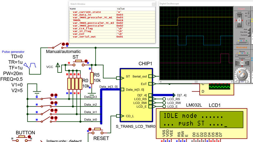 |
Fig. 11. Proteus running the application. |
Oscilloscope results can be printed using white background colour for saving ink and easy annotation.
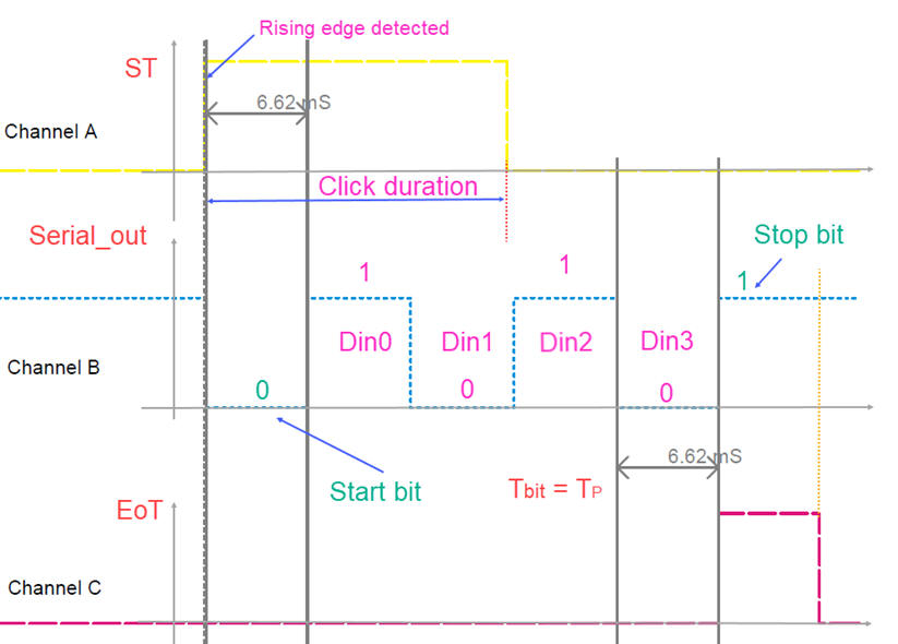 |
Fig. 12. Proteus oscilloscope waveforms when Din = "0101" |
Measure the transmission frequency accuracy.
Modify the design to use the TMR0 in 16 bit mode.
5. Report
Follow this rubric for writing reports.
6. Prototyping
| Home Term 24/25-Q1 Contact Products Electronic devices and companies Software Books Magazines Instruments DEE Library EETAC DEEL |

|
|
| Web activa des de 09/2001, @ F. J. Robert, J. Jordana. Web editat amb Microsoft Expression Web 4. El contingut és un complement als materials d'estudi del curs Circuits i Sistemes Digitals disponibles al campus digital Atenea. Llicència:Reconeixement 4.0 Internacional de Creative Commons |