|
|
Bachelor's Degree in Telecommunications Systems and in Network Engineering |
|
|
|
|||||
Chapter 2 problems |
- D2.24 - |
Rotation speed meter (tachometer) (FPGA-VHDL) |
D2.25 |
||
|
|
|||||
1. Specifications
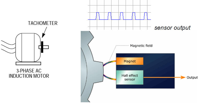
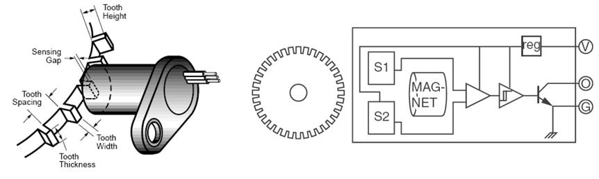
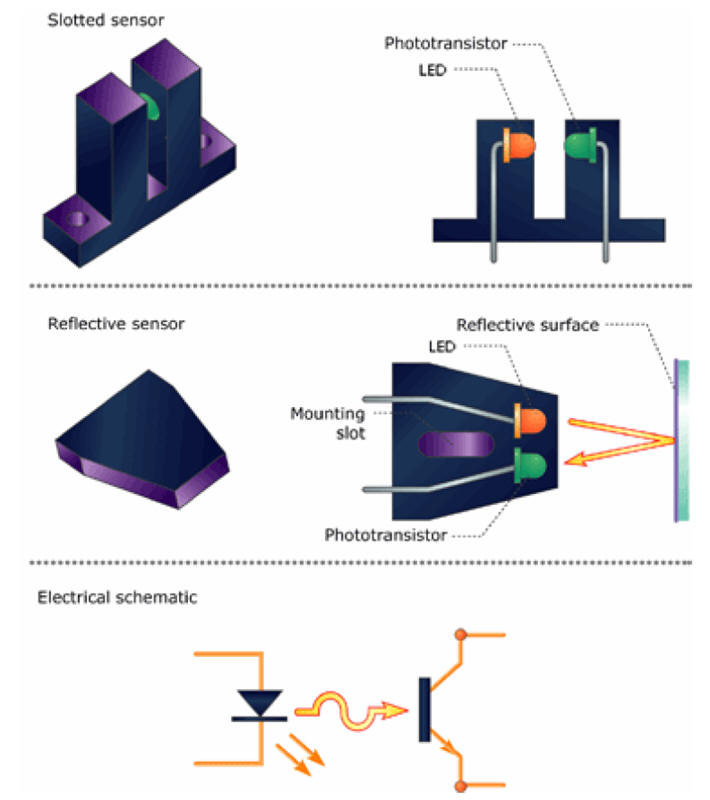
We want to build a tachometer to measure the speed of rotation of the electrical motor shown in Fig. 1 which revolves at a maximum speed of 1000 min-1 (or rpm: revolutions per minute). A geartooth joined to the motor axis turns while a magnetic sensor generates a digital pulse waveform1. The internal design of the magnetic sensor can be seen in Fig. 2. An alternative sensor, also very common but based on photodiodes and LED or optocouplers, can be seen in Fig. 3.
The same project designed programming a μC is in D3.24.
|
|
|
Fig 1. Tachometer placement attached to the motor axis and detail of the magnetic Hall effect sensor. Reference on Hall effect sensors. |
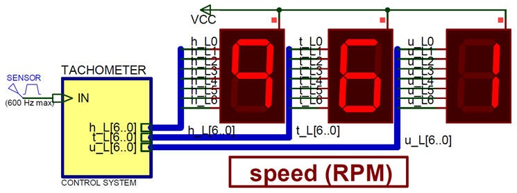
The metallic geartooth has 36 teeth and we to build a 3-digit 7-segment display to represent speeds up to 999 min-1 as sketched in Fig. 4.
|
|
|
Fig 2. Magnetic Hall effect sensor (SD1012 from www.cherrycorp.com). |
|
|
|
Fig 3. Speed sensor based on optical sensor build using optocouplers. |
|
|
|
Fig 4. 3-digit speed sensor tachometer.pdsprj diagram simulated in Proteus. |
| Home Term 23/24-Q2 Contact Products Electronic devices and companies Software Books Magazines Instruments DEE Library EETAC DEEL |

|
|
| Web activa des de 09/2001, @ F. J. Robert, J. Jordana. Web editat amb Microsoft Expression Web 4. El contingut és un complement als materials d'estudi del curs Circuits i Sistemes Digitals disponibles al campus digital Atenea. Llicència:Reconeixement 4.0 Internacional de Creative Commons |