|
|
Bachelor's Degree in Telecommunications Systems and in Network Engineering |
|
|
|
||
|
|
Traffic light controller |
|
|
|
||
Basics on synchronous FSM
1. Specifications
Design a synchronous sequential system to control the basic operations of traffic light poles in a crossroad.
 |
Fig 1. Symbol of the traffic light controller and the sketch of the crossroad where it is installed. (Visio). (Sketch and a Proteus example from a previous course). |
 |
|
The specifications of such real-world system may be quite complex, as you see in the list below, and its design has to be partitioned necessarily in phases starting from a basic system and adding some new features in each new step.
- The controller is used to cycle the traffic lights at the intersection through the prescribed colour sequence green (G) - yellow (Y) - red (R).
- Green lights also generate a dual-tone sound wave for the visually impaired.
- Circulation in Street B be must be stopped 45 s in red (which is also the Green A time).
- Circulation in Avenue A must be stopped 33 s in red (this is also Green B time). Yellow light will last for 10 s in both streets.
- Real time in seconds can be programmed using switches for setting the 8 bit binary codes (thus, a 4-channel 8-bit programmable timer is required.
- A night mode of operation will turn off red and green lights while keeping yellows flashing at a 2 Hz rate.
- Night mode is set from a real time clock signal which is active every day from 11 PM to 6 AM.
- Streets and avenues have sensors embedded in the roadbed near the intersection which are activated when a metal mass (a car or a motorbike) is over the detector. These sensors allow the system to stop the normal traffic light sequencing and block permanently (red light) the road with no cars detected (fixed-red mode).
- There are pushbuttons at every road to allow pedestrians crossing the streets in case of they are in fixed-red mode.
2. Planning
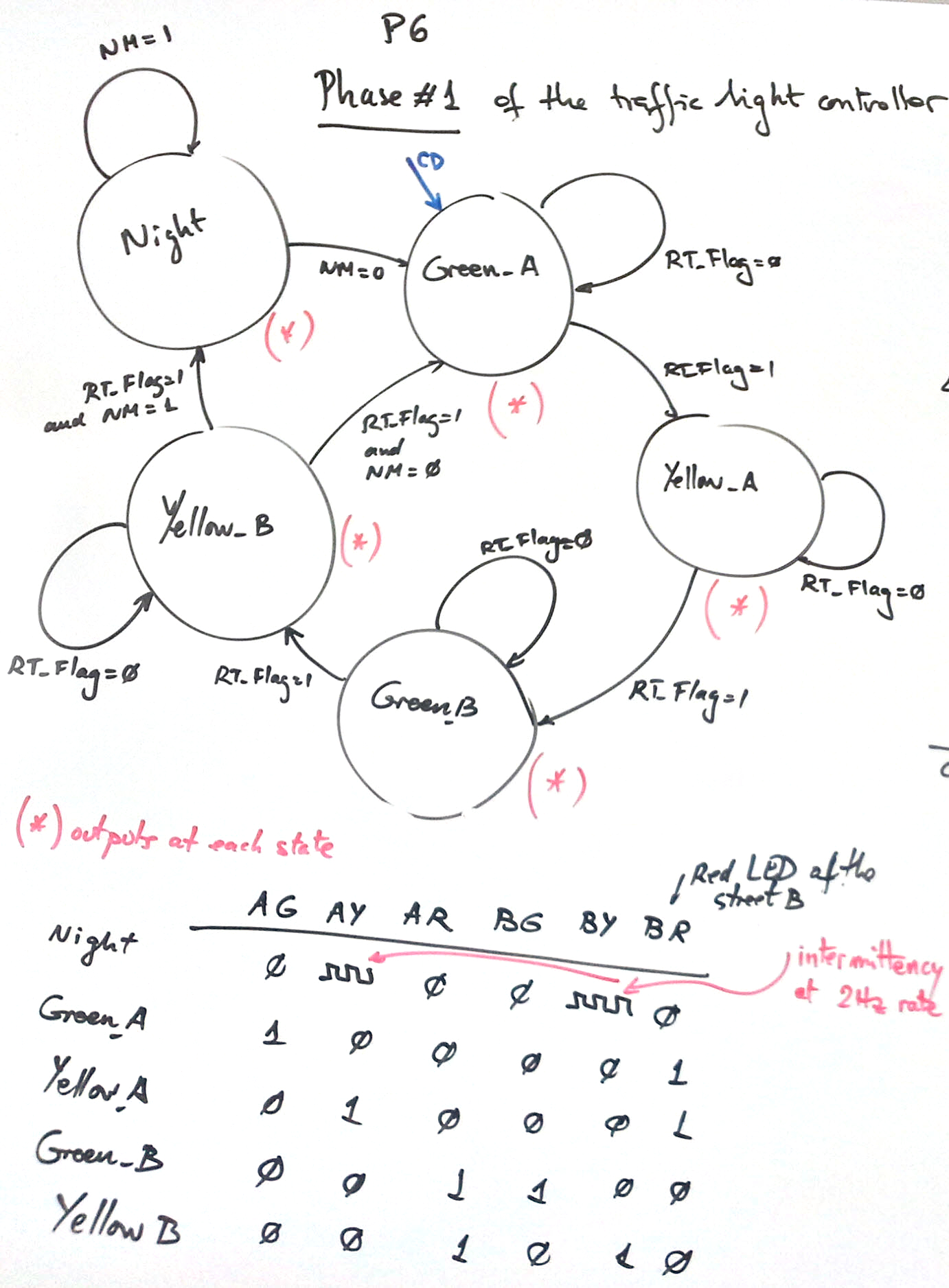
Organise the solution in several design phases. Here you are some ideas on how this kind of system may work. The first phase may be for example solving the problem using only the night mode (NM) and the real-time flag inputs using this state diagram (P6). Later in a second phase (P7), the programmable timer can be added to generate the real time flag signal. And finally in a third phase (P8), other features like pedestrian (PA, PB) and car sensors (CA, CB) may be introduced to make the system even more professional.
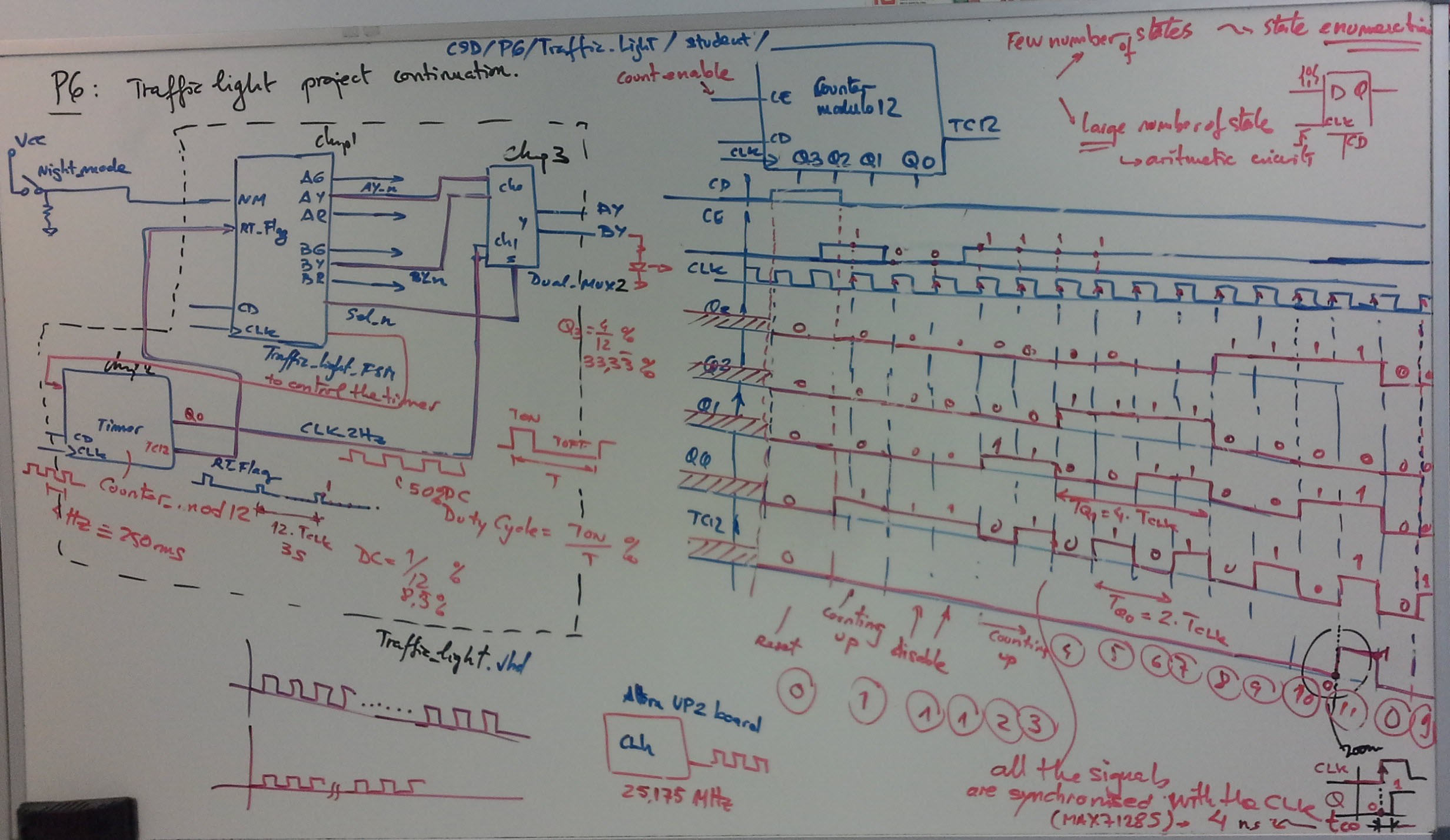
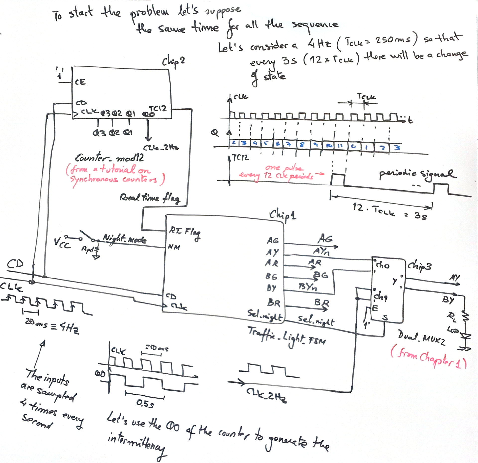
Thus, follow the sequence below to solve the design phase #1, where in order to make it simple, all the timings will be the same and generated by the synchronous counter_mod12.vhd:
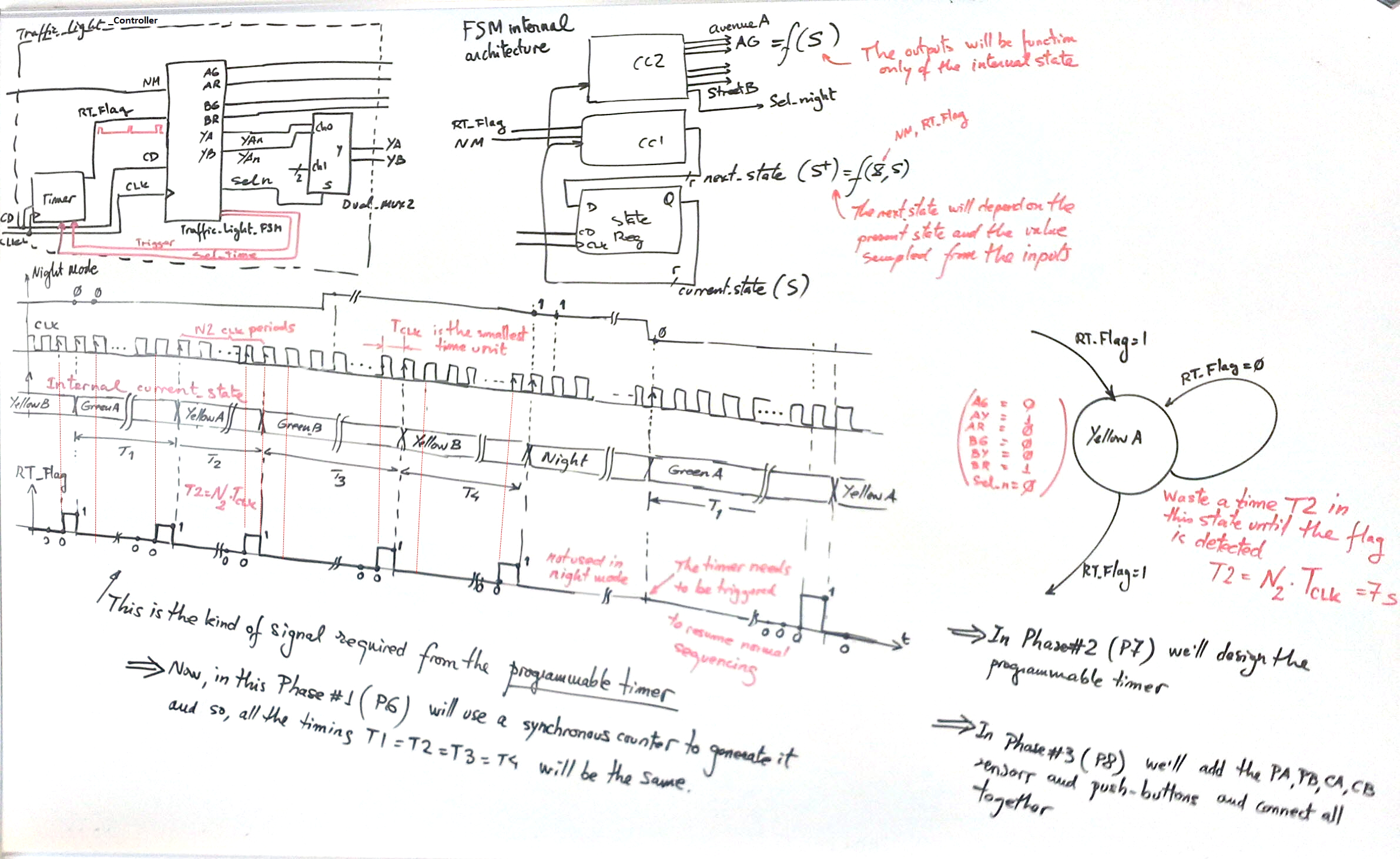
1) Imagine how a timing diagram of this system may work.
2) Run the synchronous counter tutorial to get ideas on how to generate the real-time flag signal. Thus, invent the component Chip 2 counter_mod12.vhd which is used in this case as the preliminary timer (1) and (2). For instance here you are the class discussion on how to start (Remember that the VHDL code, which is a translation of some artefact (FSM architecture, CC1, CC2, state register, signals, truth tables, flow charts, etc., is accepted to be discussed only after 1. Specs., 2. Plan, and 3.- Development). Which means that you can only study how to implement a device in VHDL once the problem is fully understood and discussed in sketches and sheets of paper with your team and the class.
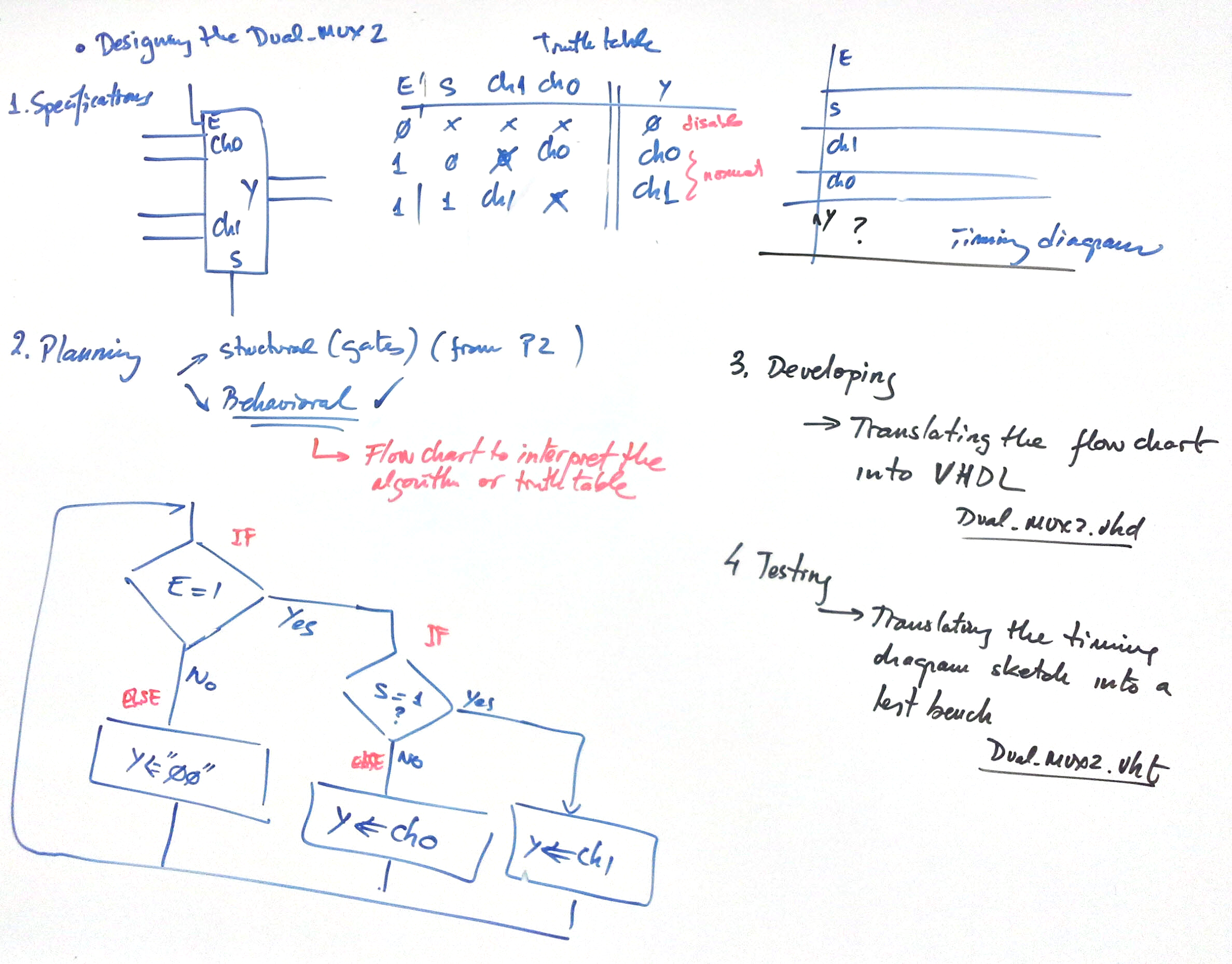
3) Invent the Chip3 architecture: Dual_MUX2.vhd. For instance here you are the class discussion on how to start (Remember that the VHDL code, which is a translation of some artefact (truth table, equations, behavioural flow chart, etc.) is accepted to be discussed only after 1. Specs., 2. Plan, and 3.- Development)
4) Run an example project to see how a FSM works (the pushbutton filter tutorial or the flashing torch) and which is its internal architecture. You can copy and adapt any of these examples to obtain the traffic_light_FSM.vhd.
5) Implement an structure of the traffic_light controller for this design phase #1. It has to include the traffic_light_FSM conponent, the Dual_MUX2 and a 4-bit synchronous counter to generate the RT_Flag signal and the yellow lights 2Hz intermittency from the system clock (counter_mod12). It'll be discussed in class. In this way, we'll get a first approximation on how the circuit may works supposing that all the traffic light times are the same. Note: You can build this top structure without finishing the architecture of the components, only the entity definition is required.
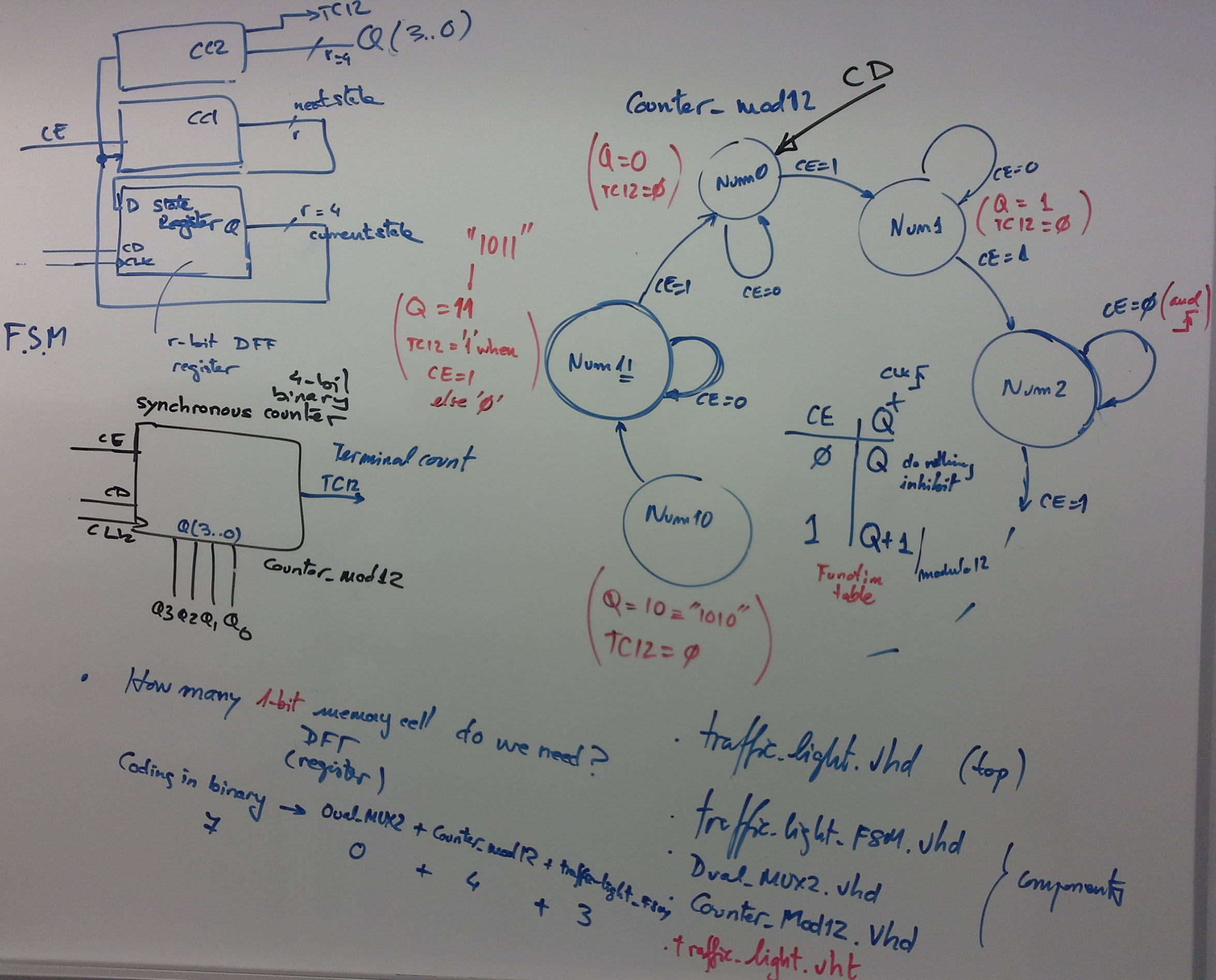
6) Solve the traffic_light_FSM component and simulate all the project:
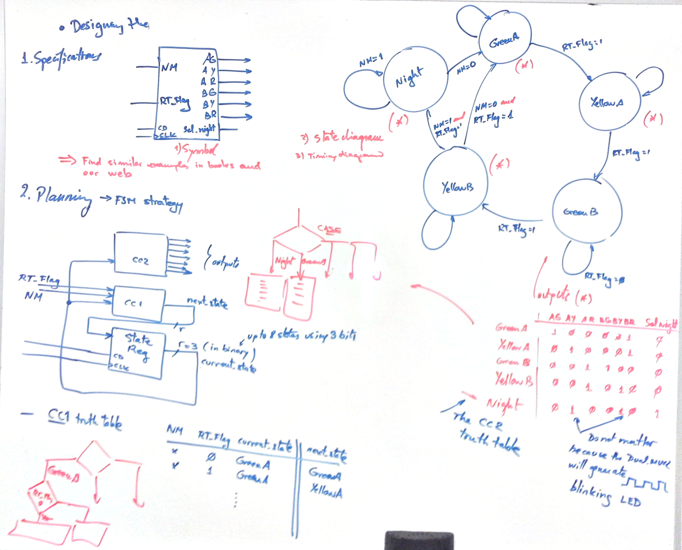
a) Figure out the state diagram . Number of states and conditions of transitions. Outputs at each state.
b) Particularise the general FSM topology to this problem. To which block (CC1, CC2, state register) is connected every input and output?. Which is the number of bits r required for coding the current and next state signals [ r = number of states if one-hot; r = (1/log 2)·log (number of states) if binary or Gray]?
c) Write the VHDL code of the finite state machine adapting an example from our web. Project folder location and file names: Traffic_light_FSM.vhd:
<disk>/CSD/P6/Traffic_light/student/(files)
d) Connect all the components (Traffic_light_FSM.vhd, Dual_MUX2.vhd, counter_mod12.vhd)) together in the top traffic_light_controller.vhd file and implement and test the system (using the traffic_light_controller.vht or traffic_light_controller_tb.vhd ). How many registers will include the complete design of this phase #1 system?
3. Development
Here there is the seed to start this project. You have the complete top file and the components with their empty architectures yet to be designed. Thus, the point is that the four files can now be compiled and so the EDA tool generates the top level schematic as represented in Fig 2, which is the translation into VHDL of the circuit represented in the whiteboard and discussed in class.
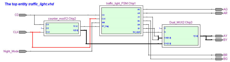 |
| Fig. 2. The top RTL view where all the components are connected. |
Write the code of the Dual.MUX2.vhd adapting a file from our web and matching exactly what you have planned previously.
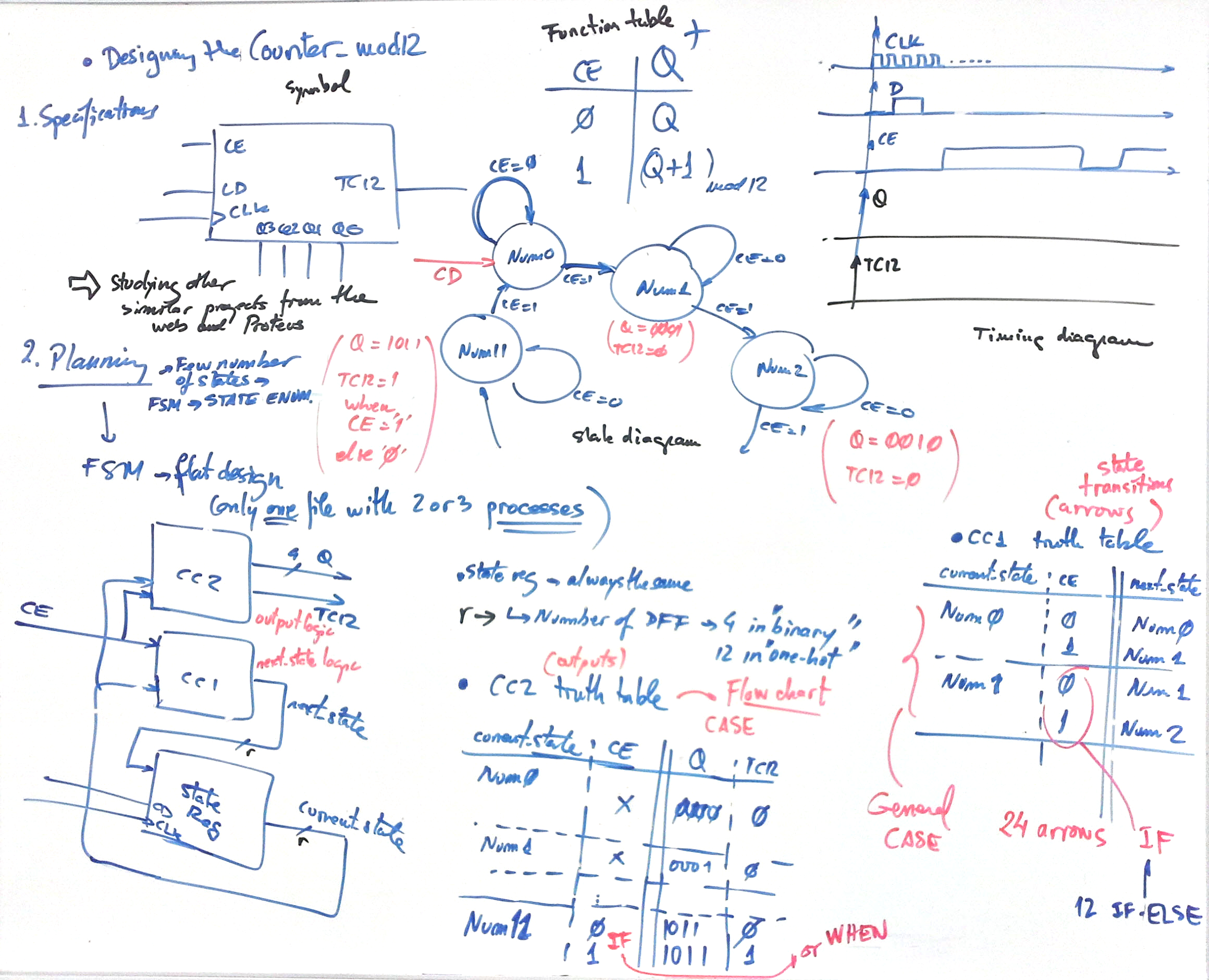
Write the code of the counter_mod12.vhd adapting a file from the tutorials and matching exactly what you have planned previously. Note that these components are also independent project that you may like to test individually.
Write the VHDL file corresponding to the Traffic_light_FSM.vhd having translated the flow charts of the CC1 and CC2 and copied the state register. Copy and adapt a previous VHDL FSM example from our web like the debouncing filter or the traffic light controller from a another former course.
A) State register. We'll use always the same VHDL code description.
B) CC2. Truth table and flow chart if a behavioural description is used, which is normally the best idea because Boolean algebra is left to the EDA synthesiser. The CC2 is required to calculate the outputs at each state.
C) CC1. Truth table and flow chart if a behavioural description is used, which is normally the best idea because Boolean algebra is left to the synthesiser. CC1 is required to calculate the next state to go after the CLK's rising edge.
Run the EDA tool to synthesise the circuit and print and comment the RTL schematic. Check the number of registers (DFF) used in the target chip and justify the value.
4. Testing (functional simulation)
Start the test bench template and add the CLK and inputs activity translating the timing diagram. Thus, to test sequential systems at least two stimulus processes will be required: the CLK and all the other inputs. Make all the timing relative to the CLK_Period constant, which is the equivalent in Chapter 2 to the Chapter 1 Min_Pulse. Any signal shorter than one CLK can not be seen (sampled correctly) by the digital system.
Complete the template test bench file named Traffic_light_tb-vhd translating a timing diagram like the one represented above in the specifications into a CLK and input signals stimulus processes.
Functional simulation. Run the EDA VHDL tool and demonstrate how the circuit works adding comments to the printed sheet of paper containing the waveforms. Your system may works like this timing diagram discussed in class.
5. Testing (gate-level simulation and timing analyser)
6. Prototyping
Use training boards and perform laboratory measurements to verify how the circuit works.
7. Report
Project report starting with the template sheets of paper, scanned figures, file listings, docx , pptx, or any other resources.
Other materials of interest
- A traffic light is one of the most used example project to introduce the topic of synchronous FSM design. Thus, you'll find it reported in many similar university courses and books. Here there is an example from the University of Berkeley (USA).
| Home Term 24/25-Q1 Contact Products Electronic devices and companies Software Books Magazines Instruments DEE Library EETAC DEEL |

|
|
| Web activa des de 09/2001, @ F. J. Robert, J. Jordana. Web editat amb Microsoft Expression Web 4. El contingut és un complement als materials d'estudi del curs Circuits i Sistemes Digitals disponibles al campus digital Atenea. Llicència:Reconeixement 4.0 Internacional de Creative Commons |