|
|
Bachelor's Degree in Telecommunications Systems and in Network Engineering. Bachelor's Degree in Aerospace Systems Engineering |
|
|
Laboratory 9: Power outputs and drivers, electrical isolation |
1. Specifications
Our goal is to drive power loads from digital circuits, we have to generate large voltages and currents while at the same time we like to use low-power microcontroller chips and peripheral for controlling applications. For instance:
- Generate an analogue output for applying sound waves to a 10 W speaker.
- Drive an electromechanical relay capable of switching mains 220 V - 50 Hz power loads such AC motors, fluorescent lamps or water pumps.
- Generate an optically-coupled PWM output for driving an isolated 10 W power LED lamp or a 12 V DC motor.
- Drive a 5 V stepper motor.
- Design the conditioning circuit for driving a +5 V servo motor.
- Study how to drive a BLDC motor.
|
|
|
Fig. 1. Example of some power driver circuits for enhancing our Arduino prototyping board. This kind of voltage and current amplifiers can be adapted to any microcontroller chip. |
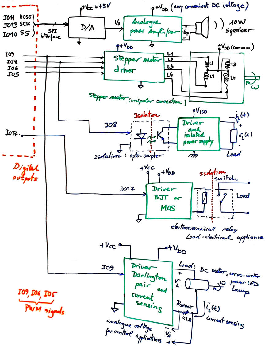
Chaining several power stages including simple or double isolation it is possible to jump from mW to kW. NOTE: ESD, transient, over-voltage and other protection and noise filtering circuits are not included; some examples will be proposed below in the EMC section.
In previous projects we have generated analogue and digital signals from microcontrollers capable of outputting some mW of power for driving small LED or needle panel meters. Thus, how to driver power loads such luminaries and electric motors? Each power load or actuator has its own physical principles and driving methods. Thus, we will review references and literature on DC motors, servo motors, stepper motors and BLDC motors to complete some example projects.
- DRV8833 Dual motor driver.
- Servo motor and how does it work. Fig. 2 shows a Proteus simulation of a hobbyist servo. It uses a 5 V 50 Hz PWM rectangular waveform that moves the motor axis from -90° (1ms, 5% DC) to +90° (2 ms, 10% DC).
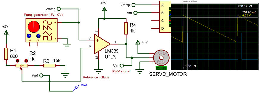 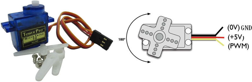 |
| Fig. 2. Example simulation of a servo-motor and the typical servo available in many Arduino and Raspberry Pi kits: Tower Pro micro-servo SG90 (ref.). VCC must be able to supply 100 mA (no load). |
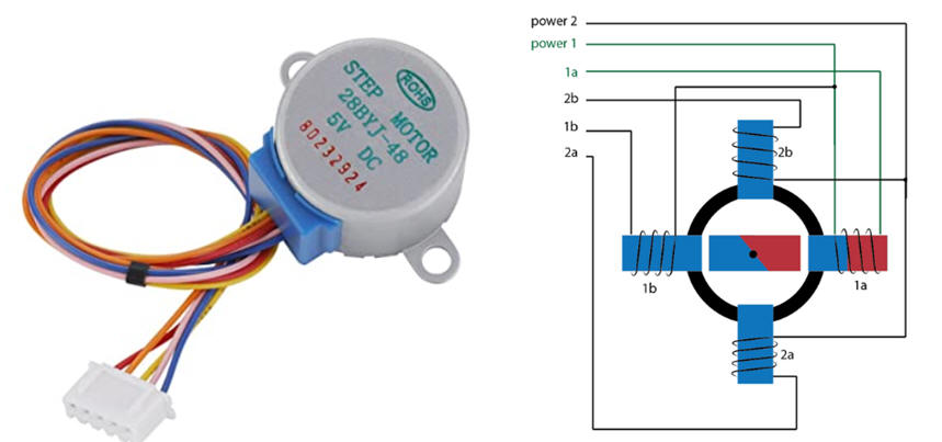 |
| Fig. 3. Example of stepper motor and conceptual model (3) |
- BLDC driver and example Arduino shield.
- Analogue class AB power amplifiers.
Power transistors as electronic amplifiers and switches
Drivers can be build using discrete MOS or BJT transistors along with some extra components for biasing and adapting voltage levels and protecting the circuits from ESD.
Power BJT complementary pair (NPN) 2N3055 - (PNP) 2N2955 (ref.). Small-signal transistor type 2N2222 - BC547.
Power NMOS IRF530 datasheet. Power PMOS IRF9530 datasheet. Small-signal N-MOS SN7002.
|
|
| Fig. 4. Example cases for power transistors. Generally, a heatsink has to be screwed to the case to keep a low operational temperature. |
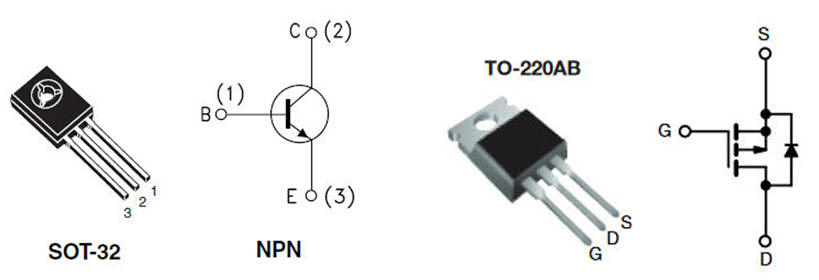
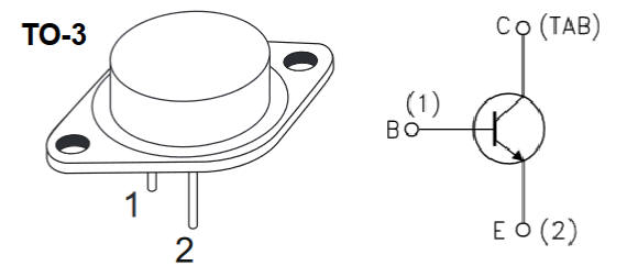
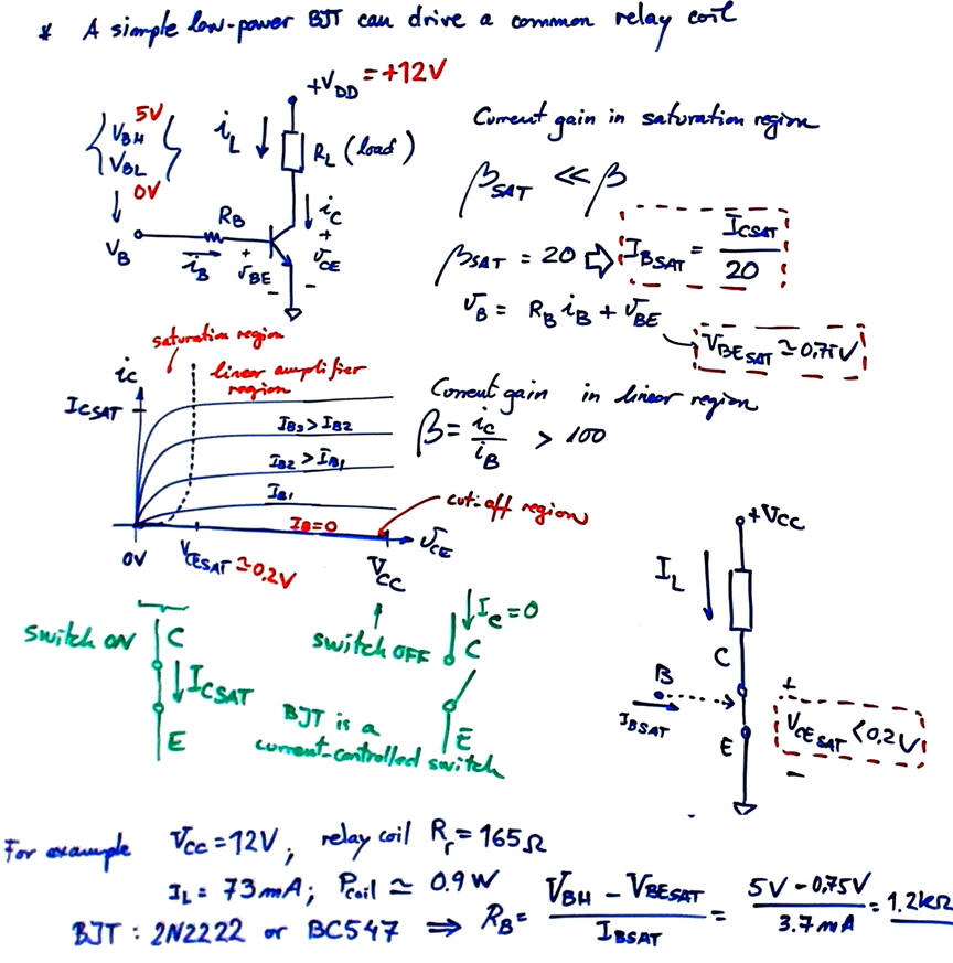
Fig. 5 explains how to use a BJT as a digital inverter to adapt voltages and amplify currents for power loads, such a relay coil.
|
|
| Fig. 5. How to bias an NPN BJT to be used as a digital switch. Similar equations are derived for PNP BJT. |
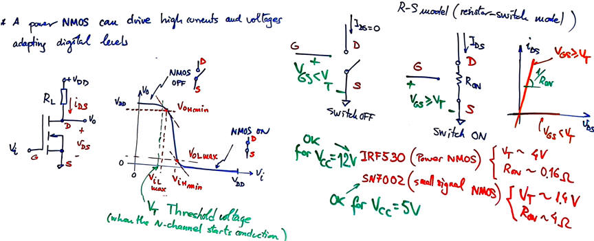
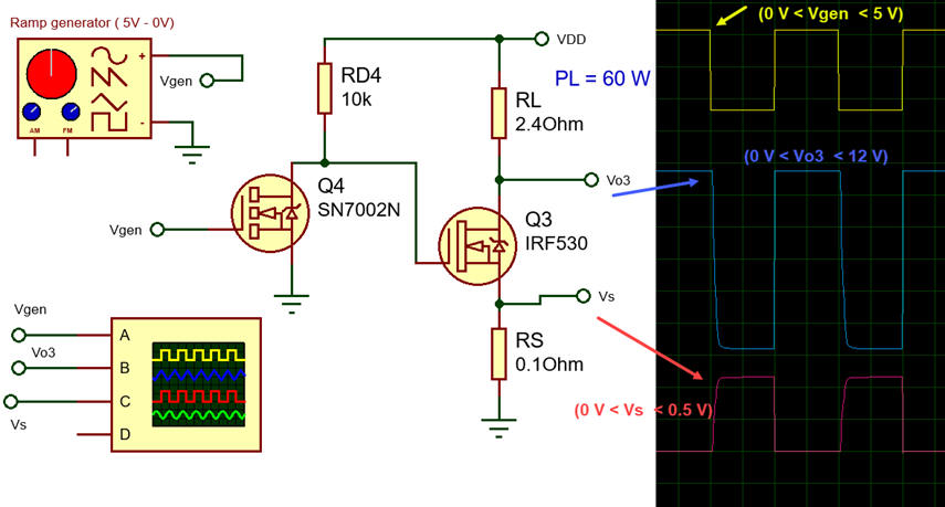
And Fig. 6 shows the way an NMOS is used as an almost perfect voltage-controlled switch. If VDD and VCC are not similar, the power MOS requires biasing its gate terminal (G) using an small signal BJT or NMOS transistor.
|
|
| Fig. 6. Transfer input-output function and simple transistor models on how the enhancement N-channel MOSFET behaves as a digital switch. There is also represented an example on how to adapt the digital level-high from VCC = 5 V to VDD = 12 V driving at the same time a 60 W resistive load. Simulation file: MOSFET.pdsprj. |
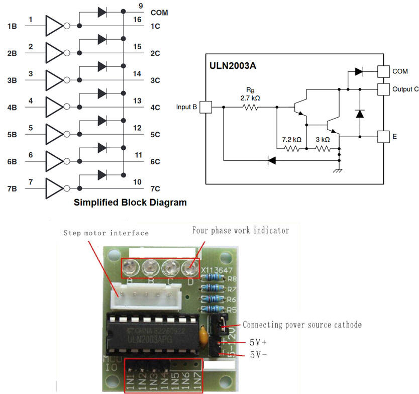
It is also possible to use integrated drivers such ULN2003A
|
|
| Fig. 7. The chip ULN2003A from Texas Instruments is a 7-channel NPN Darlington BJT pair. For instance, we can use four channels to drive an stepper motor, as proposed in this kit. |
Optical isolators
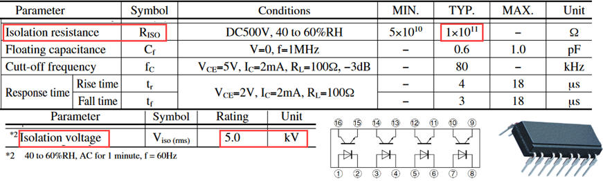
Power drivers may include opto-isolators for breaking ground loops and providing high voltage protection. They are widely available in industry. These 4N25 and PC847X are example chips. They use IR LED and phototransistors in a single encapsulation to withstand up to 5 kV. Electrical isolation resistance is extremely high: 100 GW.
|
|
| Fig. 8. Example of PC847X opto-coupler characteristics. |
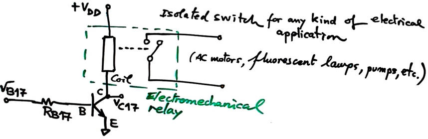
Electromechanical relays
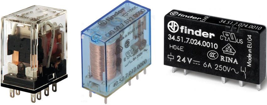
Air is also used as a perfect insulator for breaking ground loops and activating high voltage loads, as in electromechanical relays driven by a coil. These are examples of typical DC electromechanical relay (ref.)
|
|
| Fig. 9. Electromagnetic relay to switch power loads for example connected to the mains power plug. |
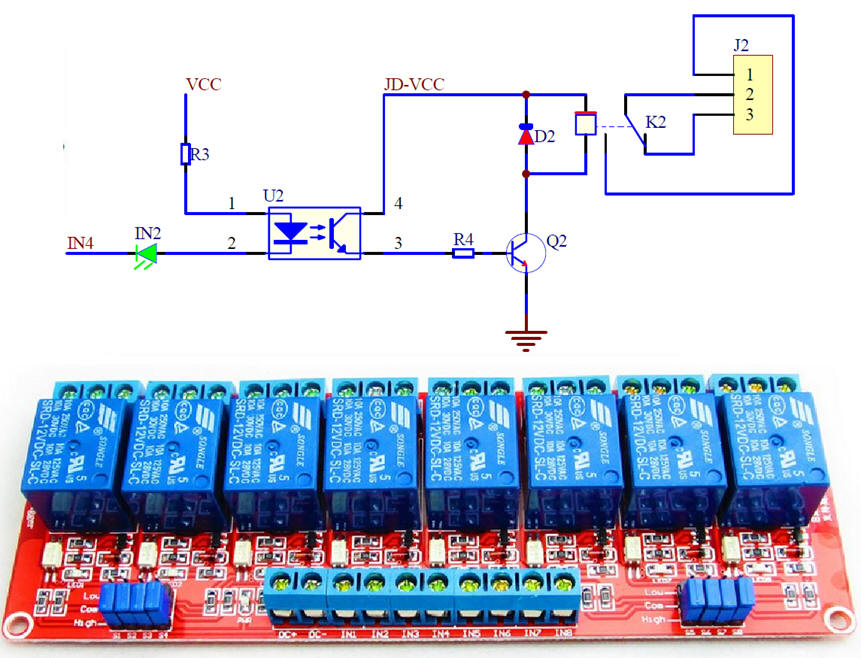
It is possible to find easily boards that contain multiple channels.
|
|
| Fig.10. 8-channel board of optically isolated relays (ref.) |
Transformers
Transformers, ferrite wirings and coils along with modulated signals are also widely used for transferring not only power but control and sensing signals. They can be used in front-end applications as isolation amplifiers covered in LAB6 and also to drive power loads.
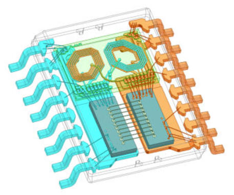 |
Fig. 11. Integrated transformer provides a galvanic barrier, as shown in this white paper on isolation technologies from Texas instruments. |
2. Planning
Hardware
Let us calculate a simple BJT driver circuit.
|
|
| Fig. 12. BJT buffer for driving a relay. |
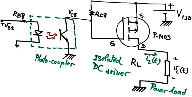
We can use the 4N25 optocouple and a PMOS IRF9530 to mount the power driver presented in Fig. 13. Calculate the minimum resistive load (RL W) that can be connected while keeping the temperature of the PMOS below 100 °C without heatsink.
|
|
| Fig. 13. Using an opto-couple to driver a ground-referenced load. |
|
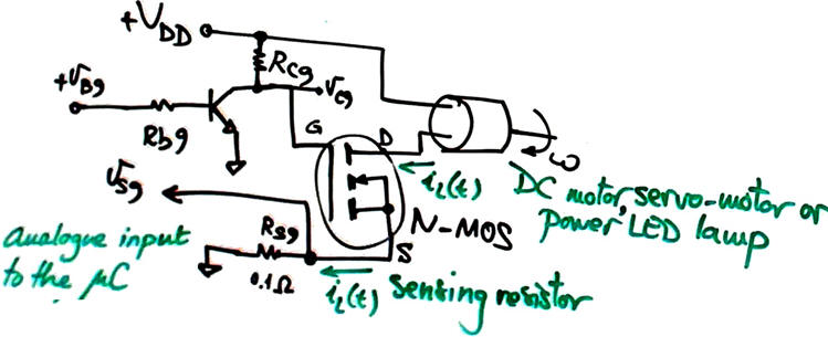
|
| Fig. 14. Driving a BJT and an N-MOS for a high-referenced load. Current sensing to be used as a microcontroller control input using a shunt resistor is also pictured. In high performance applications, current measurement can also be made contactless; read this extraordinary paper from Analog Devices. |
Software
To start applying simple power drivers, for instance for driving a 220 V incandescent bulb, we can use the same LAB8 software application. We are only interested in how to transform computer '0' and '1' into high currents or voltages.
However, if we like to drive for instance an stepper motor (Fig. 3), software has to be modified and prepared so that the computer generates the specific sequence required by this kind of actuator. Sometimes, processing such signals requires much computer's processing time and thus specialised controllers (another microcontroller or FSM) have to be developed to fulfill this task. For example: this is simple driver ULN2003A that can be used for stepper motor coils, and this is a complete controller.
The same happens when the motor requires advanced control algorithms, for example BLDC motors. Arduino simply sends control orders to a highly specialised circuit. This is an example chip from Infineon: TLE9879QXA40.
Connect a servo-motor to the VDD power supply and drive it directly from a digital output. Generate the required PWM waveform and characterise the motor current consumption when the shaft is sweeping continuously an angle of 135°.
Initial project location:
C:\EMC\LAB9\Temp_LCD_DA_PD\(files)
Generate a new project in a different location when you add a new actuator.
3. Development and 4. testing
Hardware
This is the Temp_LCD_DA_PD.pdsprj enhanced with some of the power drivers planned in this project.
Software
Topics in EMC
ESD, transient, over-voltage and other protections and noise filtering circuits were not included in the circuits studied in this project. These techniques for protecting semiconductors and chips and also for providing EMC will be included in this section.
We can proceed enhancing the previous LAB8 PCB prototype board adding the digital power drivers conceived in this project as shown in Fig. 15 (LAB9_PCB_v3.zip). This is the complete schematic: LAB9_board_schematic. This is the silkscreen layer component placement in scale 1:1 (pdf).
 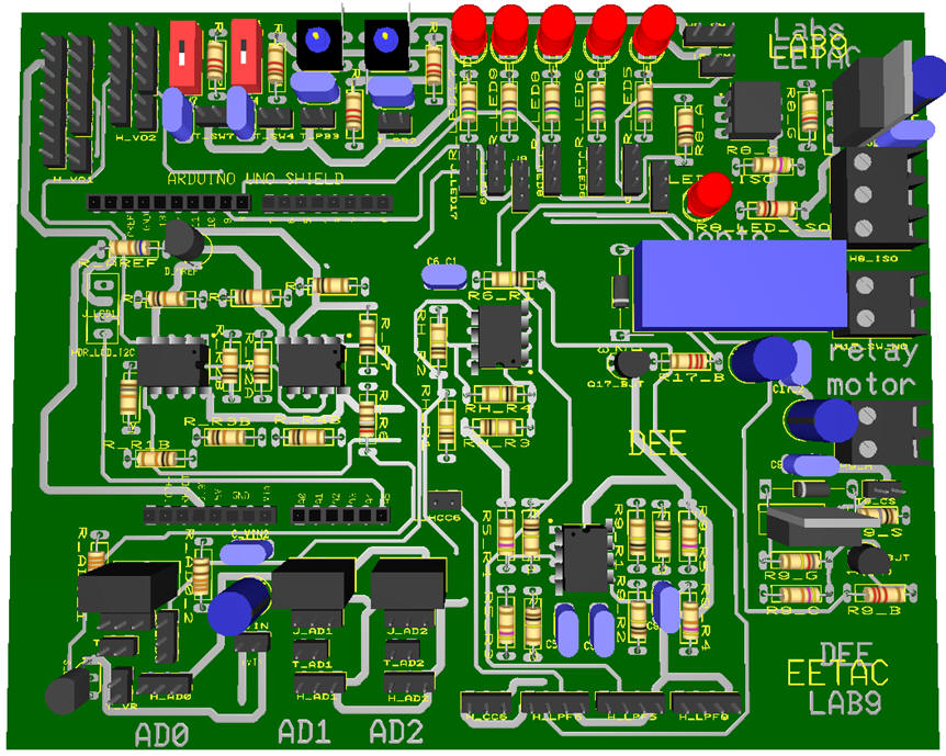 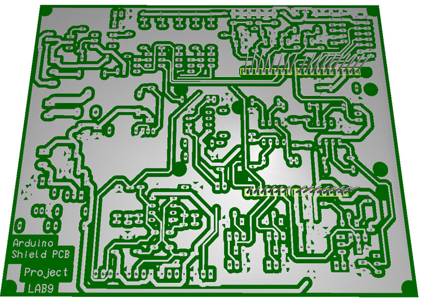 |
| Fig. 15. Component placement and 3D view of the prototype board completely wired including the power plane connected to GND. |
It is also time to study our final tutorial project PRJ1 on a temperature control system. We can use this board as the controller for acquiring chamber temperature and driving the thermoelectric actuator.
6. Reporting
Studying and reporting this LAB9 means designing a given driver as a project using this page notes and organisation as a guide on how to proceed. For instance: design an optoisolated driver for a 100 W, 12 V power LED.
1) Specifications. Use diagrams, graphics, bullet list, books and references of similar industrial applications.
(2) Planning. What circuits may work for driving a power LED? Propose several alternative circuits discussing advantages and drawbacks.
(3) Developing and (4) testing the plan. Select a circuit, calculate its components and simulate it to check that it works as expected in the specifications. Take pictures or print graphics from simulators and analyse and discuss the results.
(5) Prototyping. Solder the circuit in an universal protoboard and experiment, performing measurements, characterising the circuit. Discuss how the circuit adjust to the specifications.
Annex: Power dissipated in resistive loads driven by PWM waveforms
Actuators transform electric energy into light, rotating force or any other energy form. In a resistor or a heating element we are interested in power consumption dissipated into heat.
|
|
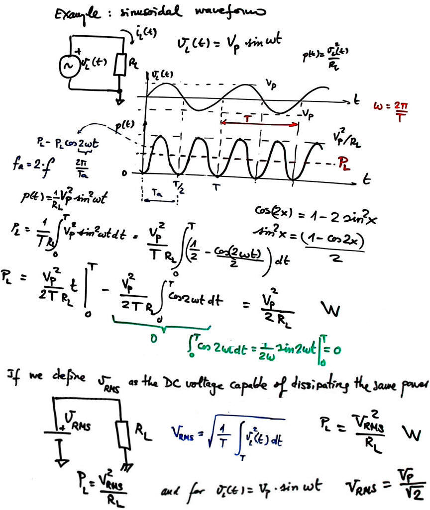
| Fig. 1. General formulation and the specific case of sinusoidal waveforms. The instantaneous power cosinusoidal component at fa = 2f has an average value zero. |
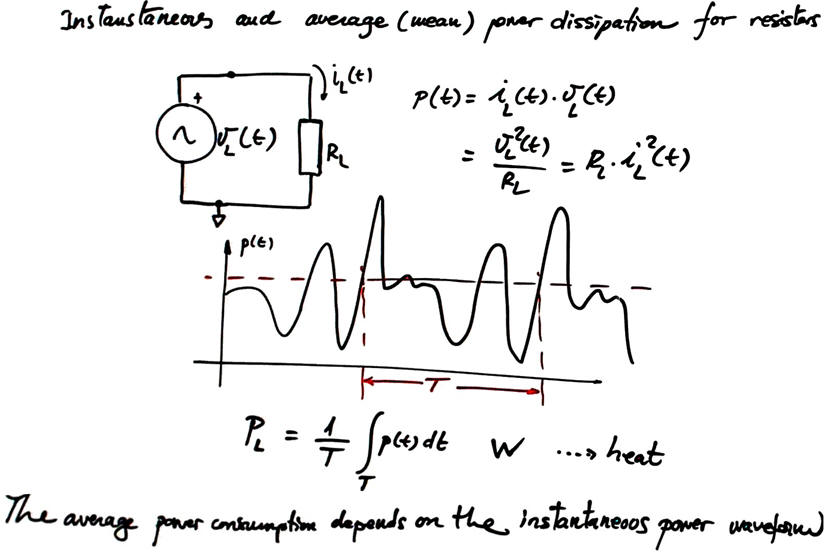
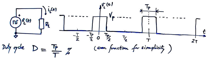
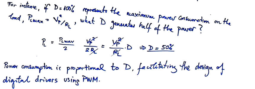
Drivers using transistors as switching elements handle rectangular waves with digital values '1' and '0'. In many applications high frequency PWM waves are used to drive and control actuators depending on the duty cycle (D). Therefore, we have interest in finding the average power PL for this specific waveform.
|
|
| Fig. 2. Rectangular digital waveforms pulse width modulated. |
As in the sinusoidal waveform in Fig. 1, the way to deduce the average power PL dissipated by the load when driven by a vL(t) PWM waveform is to find its root-mean squared (RMS) value because it is directly connected to the electrical power definition.
|
|
| Fig. 3. Rectangular digital waveforms pulse width modulated. |
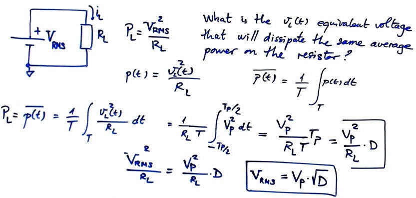
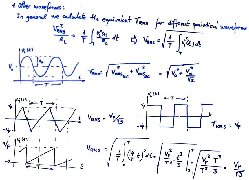
The same concept is applied when calculating the power consumption for any other periodical waveform.
|
|
| Fig. 4. Calculating the VRMS for other periodical waveforms allows as to determine the average power consumption of resistive loads. |
| Home Contact Electronic devices and companies Books Magazines Instruments Digsys Library EETAC DEEL |

|
|
| Web activa des de 01/2023, @ F. J. Robert. Web editat amb Microsoft Expression Web 4. El contingut és material de referència per al disseny d'equips electrònics. Llicència:Reconeixement 4.0 Internacional de Creative Commons |