|
|
Bachelor's Degree in Telecommunications Systems and in Network Engineering |
|
|
|
|||||
Chapter 2 problems |
- A2.1 - |
Analysis of a synchronous circuit (Circuit_E) |
|
||
|
|
|||||
1. Specifications
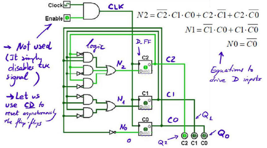
Fig. 1 represents a circuit based on D_FF found browsing Internet. Let us name it Circuit_E. Enable input is not required because it is simply a CLK blocker when '0' freezing the circuit activity (in P7 we will present better methods for inhibiting, disabling or stopping a circuit activity without connecting the special CLK signal). In Fig. 2 we have redrawn and adapted it as usual to our conventions and naming style so that we can use our tools to analyse it.
 |
|
Fig. 1. Circuit based on D_FF and logic gates. |
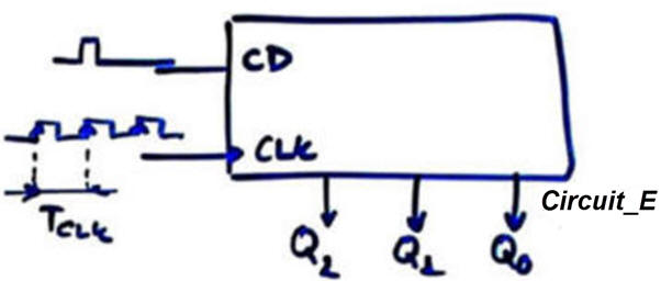
Determine how does the circuit work, meaning finding the output vector Q(2..0) using our three analysis methods. Measure propagation delays CLK to output (tCO) and deduce the maximum CLK frequency fMAX that can be applyed to the circuit.
2. Planning
Method I. Handwritten analysis to draw the circuit's timing diagram and determining the outputs. In our LAB5 session you can study similar circuits.
Two analysis steps: (1) analyse one D_FF, (2) analyse the complete circuit. Here it is necessary to determine the three truth tables for the combinational circuits before applying them on calculating N1, N2 and N0 outputs to be sampled on the CLK's rising edges.
Use this project location to save your paper solution, class notes, pictures, theory, etc.:
C:\CSD\P5\Circuit_E\paper\(files)
Method II. Proteus capture and electrical simulation. In our LAB5 session you can learn some experience using Proteus and find circuits to copy and adapt using the corresponding library of components. Apply the planned stepped procedure for capturing and analysing your circuits.
Proteus components library options:
option #1.: LS-TTL
option #2.: CMOS
Project location:
C:\CSD\P5\Circuit_E\proteus\(files)
Method III. VHDL synthesis and simulation. In our LAB5 session you can find circuits to copy and adapt to VHDL using our hierarchical multiple-file plan C2.
What is the maximum CLK frequency when picking a target chip MAXII EPM2210F324C3?
  |
|
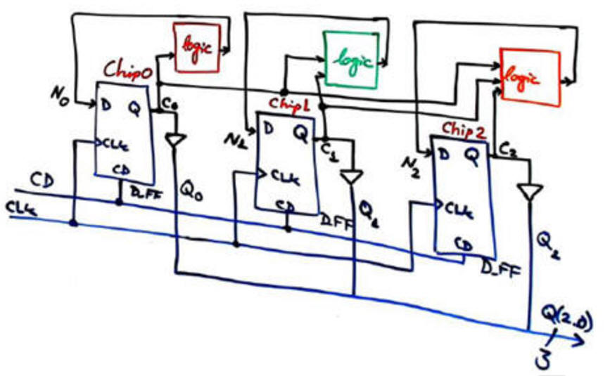
Fig. 2. Circuit_E to be analysed using our three methods. |
CPLD or FPGA target chip options:
option #1.: MAX II
option #3.: Cyclone IV
Project location:
C:\CSD\P5\Circuit_E\VHDL\(files)
| Home Term 23/24-Q2 Contact Products Electronic devices and companies Software Books Magazines Instruments DEE Library EETAC DEEL |

|
|
| Web activa des de 09/2001, @ F. J. Robert, J. Jordana. Web editat amb Microsoft Expression Web 4. El contingut és un complement als materials d'estudi del curs Circuits i Sistemes Digitals disponibles al campus digital Atenea. Llicència:Reconeixement 4.0 Internacional de Creative Commons |